OpenWrt: Extend an existing wifi with a guest wifi network
OpenWrt on a TP-Link RE450
Recently a Wifi repeater I setup years a go was reset by accident and I lost the configuration which was providing extended wifi coverage and guest wifi on a TP-Link RE450. Reconfiguring the setup cost me much more time than I am willing to admit, thus I wanted to share the basics in order to be prepared next time. Also I have a backup now.
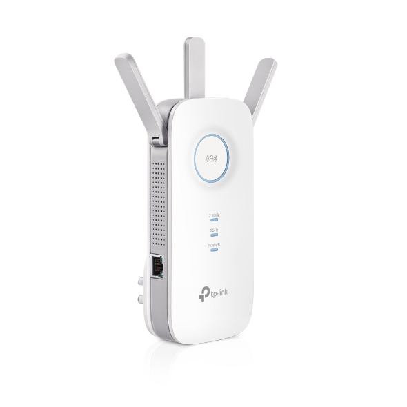
The TP-Link RE450 v1.1 (Image from TP-Link)
The TP-Link 450 is a pretty nice and affordable device which has two different wifi bands (5Ghz, 2.4Ghz). You can get it for around 50 Euros and it comes with three antennas and an ethernet port. Also it can run LEDE / OpenWrt, an open source firmware for embedded systems, such as routers and wifi extenders. The history of LEDE and OpenWrt can be read here, in this article I will call the software OpenWrt altough the interface still shows LEDE. In this article I will refer to the RE 450 as router.
Connecting to the router
Since this router will be embedded into an existing computer network, it is essential to give it a unique IP in a unique subnet.
I have decided to assign the IP address 192.168.2.1 and the subnet 255.255.255.0 to the router.
The existing network is a wireless network called Wifi with the subnet 192.168.1.1/24.
Our plan is to add a guest wifi network 192.168.3.0/24 with its own SSID called Guest and its own password.
Clients from the guest network should not be able to access any other devices within the guest network and also not be able to access any clients from the existing network.
After installing the firmware, the router will have the default address 192.168.1.1.
In order to avvoid a clash with the existing Wifi network, I attached the router with an ethernet cable to the computer and disabled wifi on my computer during the setup.
I then assigned a static IP address 192.168.1.2 for my PC using the same subnet.
And while I am already at it, I created a second ethernet profile using the address 192.168.2.5 to switch to the desired subnet once the router is configured.
Now you can easily switch between the subnets.
Installing the firmware
The first task is to get rid of the proprietary firmware and install OpenWrt. There are many instructions out there, it is important to verify the firmware and device version with great attention. Otherwise you might produce a 50 Euro paperweight of waste weekends (been there.) In case you have an older version installed, please consider updating.
For this article, I upgraded from LEDE 17.01 to a more recent OpenWRT release 19.07 and downloaded this particular release.
For the initial setup, open up a browser and go to 192.168.1.1.
Basic setup of the router
We now have installed OpenWrt on the router and can begin to configure it. You will be greated by the OpenWrt interface and advised to set a password.
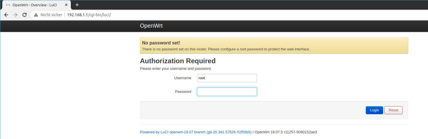
The first login.
We follow the advice and set a good password.
Next we will set a static IP by going to Network > Interfaces and edit the existing LAN interface.
This is obviously the ethernet connection we are connected to and we want to make sure we always find this device with the static ip 192.168.2.1 in the standard subnet.
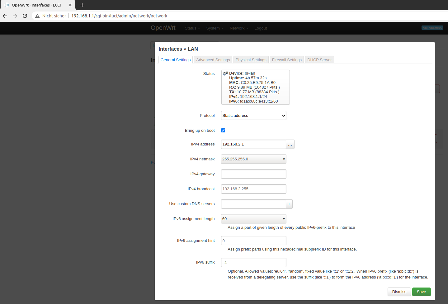
Assign a static IP
Always save and apply thanges. Afther this change you have to switch to the 192.168.2.5 profile we created earlier so that you can access the router again.
Now when we have logged in at 192.168.2.1 with our new password, we should be greeted with the OpenWrt Luci Web interface.
Setup the interfaces and wifi networks
THe first step is to connect to the existing Wifi network, so that we have a working internet connection on the router for downloading updates.
Go to Network > Wireless. You will see the default wireless interfaces called OpenWrt for both devices (3.4 Ghz and 5Ghz).
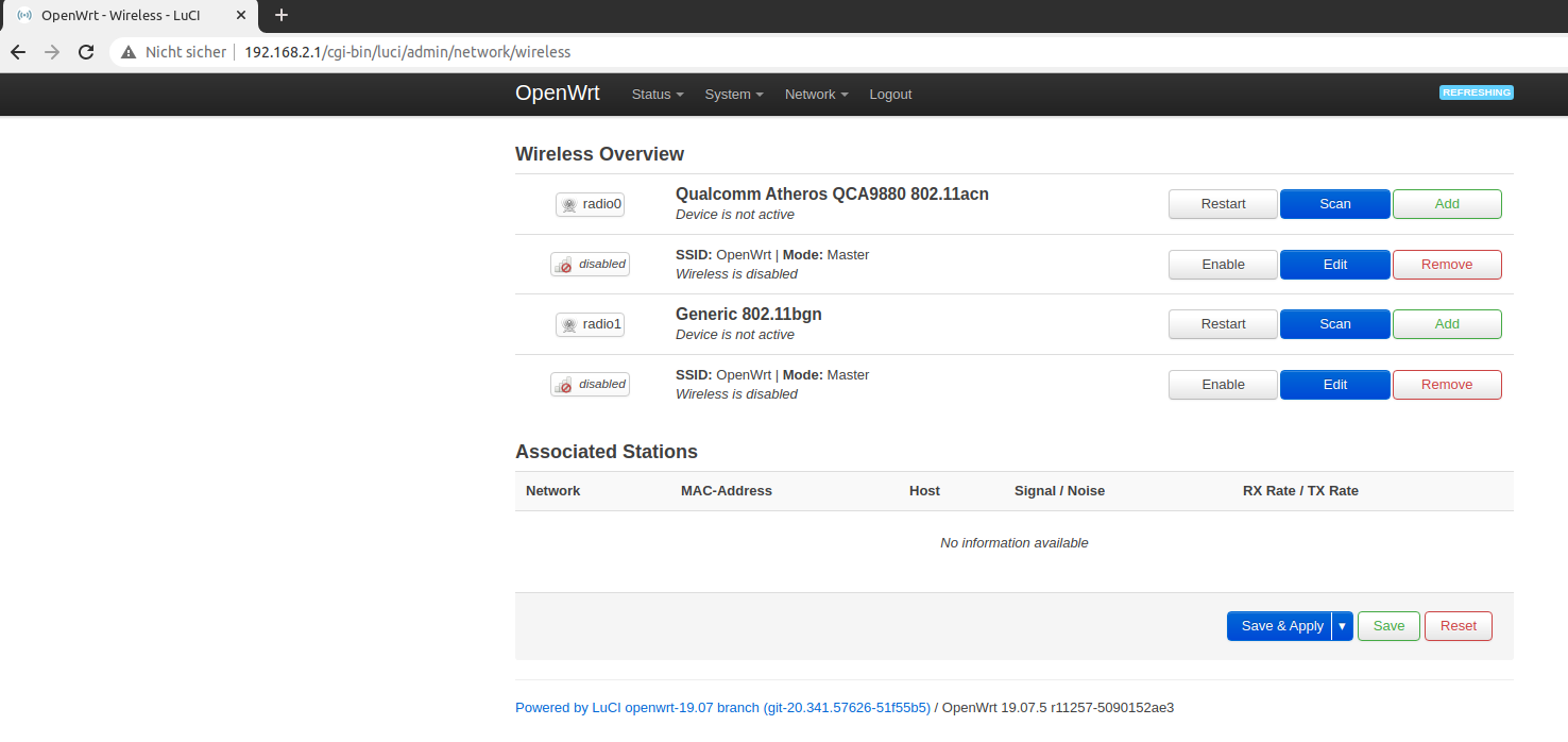
The default Wifi interfaces
Remove them so that you reach a clean state.
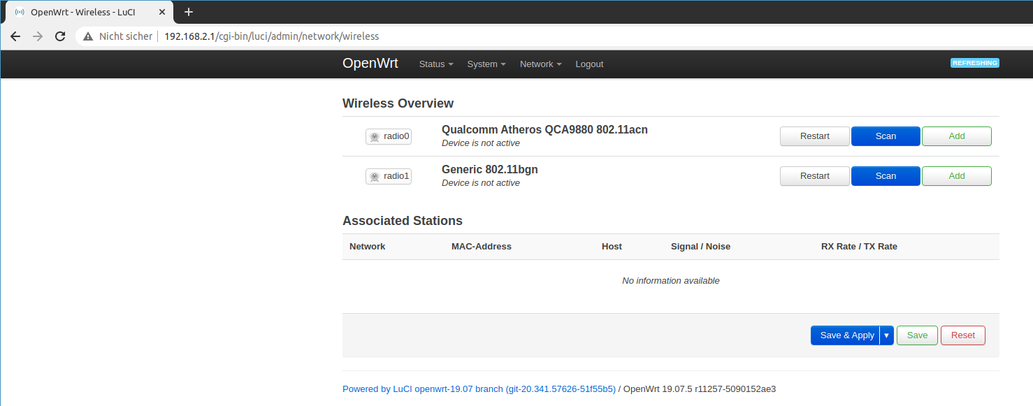
No wireless interfaces, only devices
Depending if your existing wireless network is on the 5Ghz band or the 2.4 Ghz band, use the appropriate device and click scan network and select the existing network.
Obviously you need to be in range to see the network.
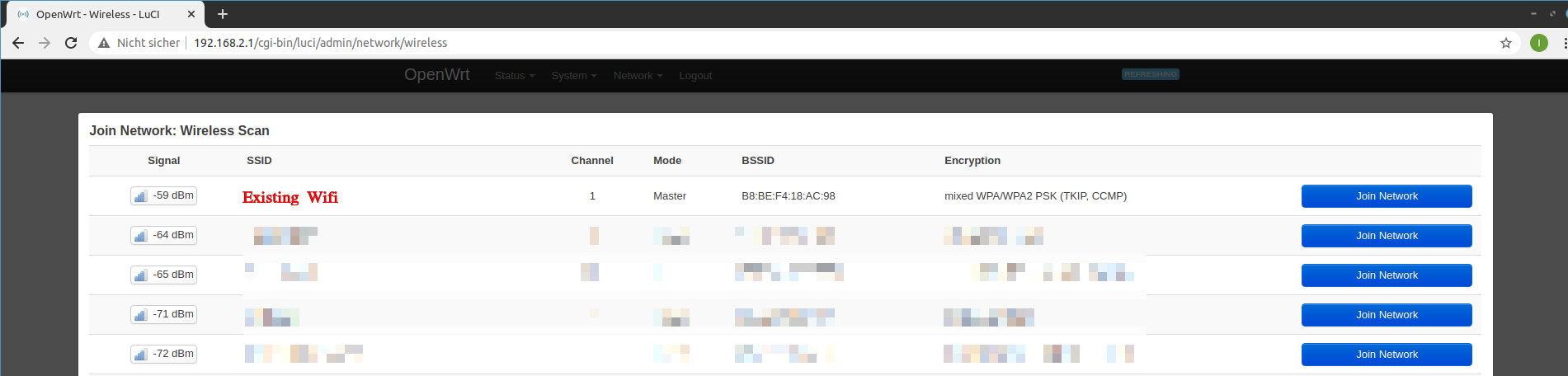
Join the existing Wifi network
You will then be promped with a details page where you enter the passphrase for the existing network and where you can select the name of the new network.
This is maybe a bit confusing, because this will create a new interface instead.
Add the name wifi.
On the tab firewall settings, add this network to the wan zone.
This is the crucial step, because the existing wifi will act as the Internet uplink for the guest network.
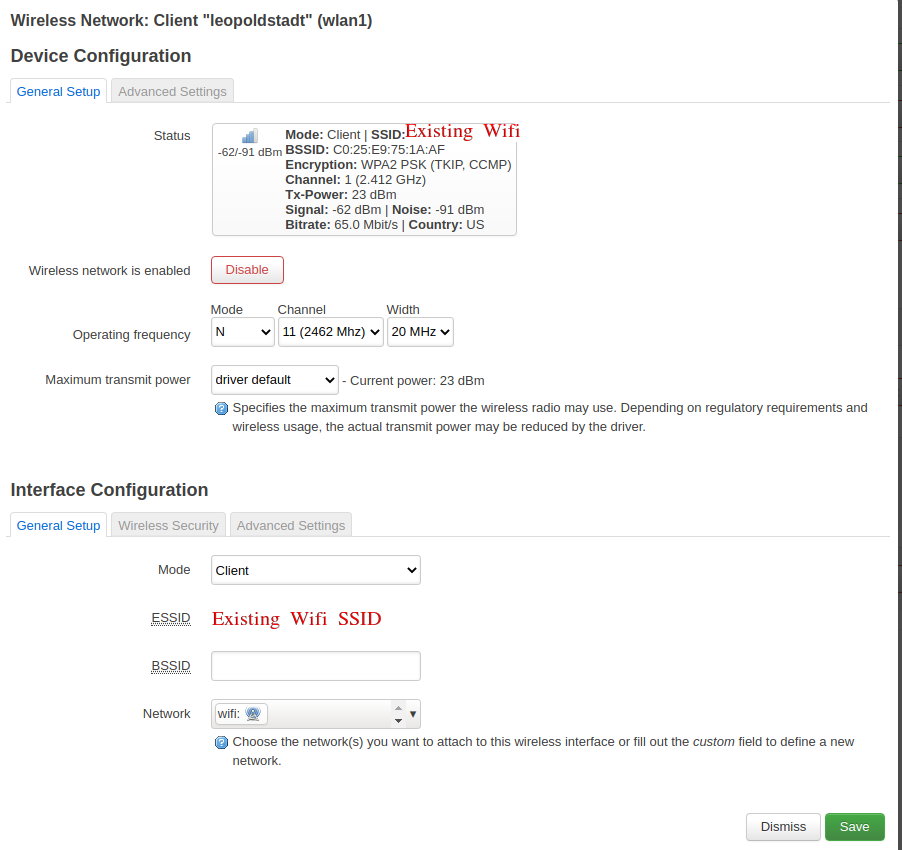
The joined, existing wifi network
Make sure to save and apply.
You should then be able t ping any web page using Network > Diagnostics.
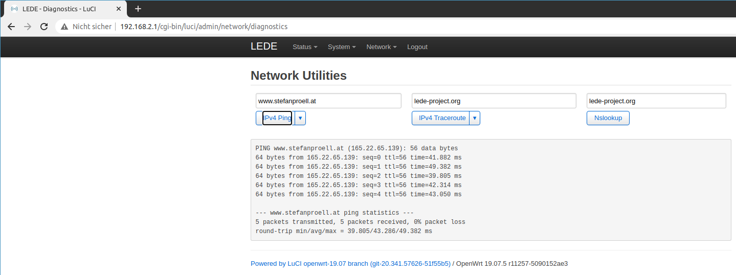
Testing ping
If this works it would be a perfect time to make a backup of the configuration.
Setup the Guest Wifi
The guest wifi also needs a new interface. Thus go to Network > Interfaces and click add new.
Select static IP address and assign the name guestwifi.
Leave interface unassigned for now.
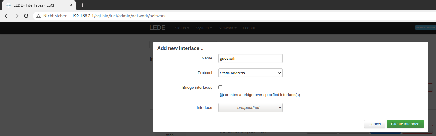
Add the guest interface
On the next page, define a static address. This time we will use 192.168.3.1 and the default subnet 255.255.255.0.
Also you should add a public DNS server like 1.1.1.1 or 8.8.8.8.
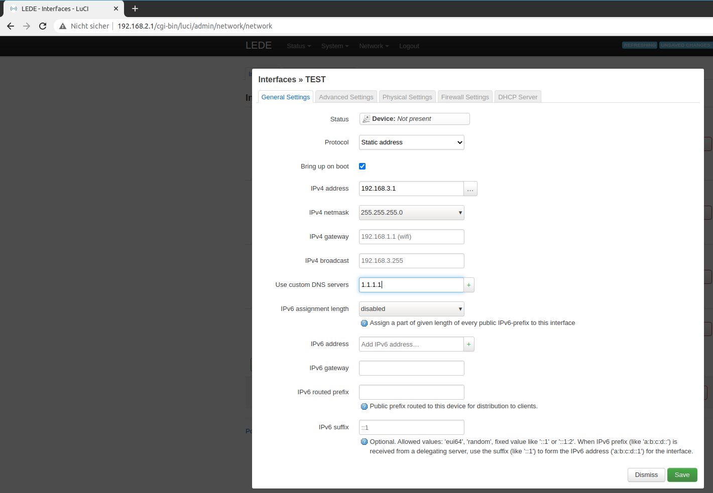
Set a static address.
Then click on the firewall tab and create a new zone guestwifi.
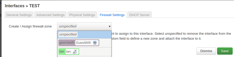
Add a new firewall zone
Then click on the DHCP server tab and enable the service.
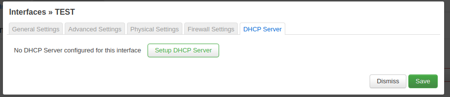
Enable DHCP service.
Review the settings and save the changes.
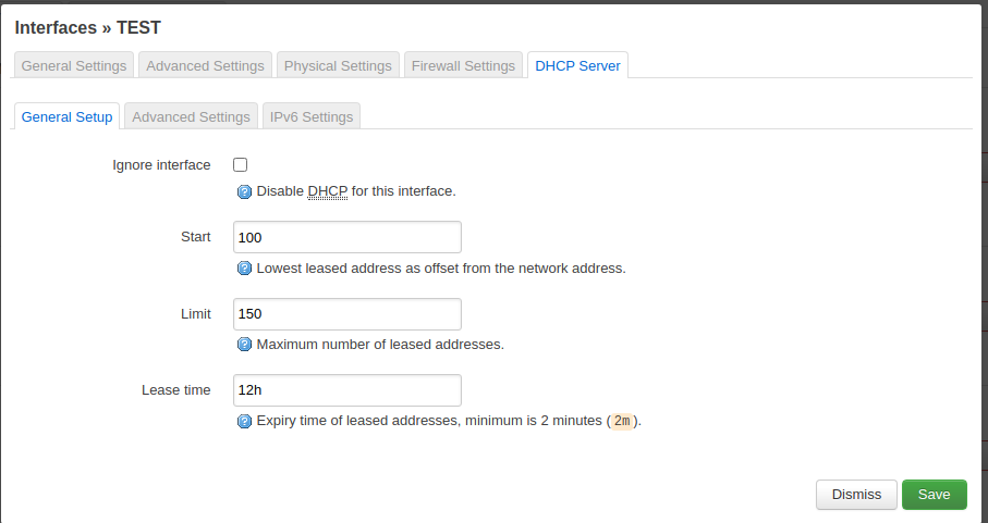
The DHCP settings can remain as they are.
Every guest will then get an IP address from the 192.168.3.1 subnet.
Save and apply.
Then proceed to Network > Wireless again and create a new wireless guest network.
I used the second antenna device to achieve this.
Click on add and pick Access Point for the mode and give it a name, for instance Guest.
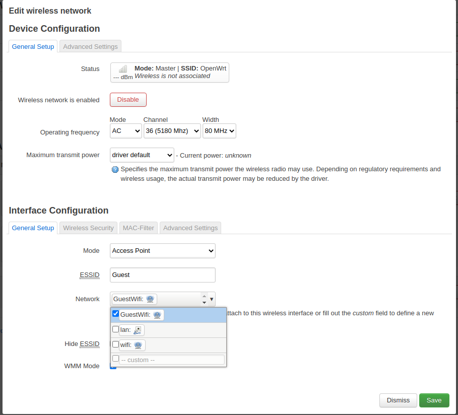
Add the guest network.
Then - and this is very important - go to the Wireless Security tab and pick WPA2 as the encryption standard and set a password you can share with your guests.
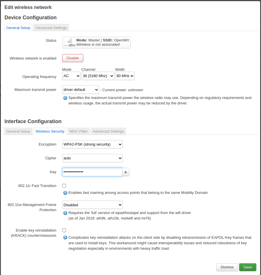
Set a password and enable encryption.
The last step is to enable client isolation in order to prevent that your guests try nasty things on each other. You find the setting at the advanced tab.
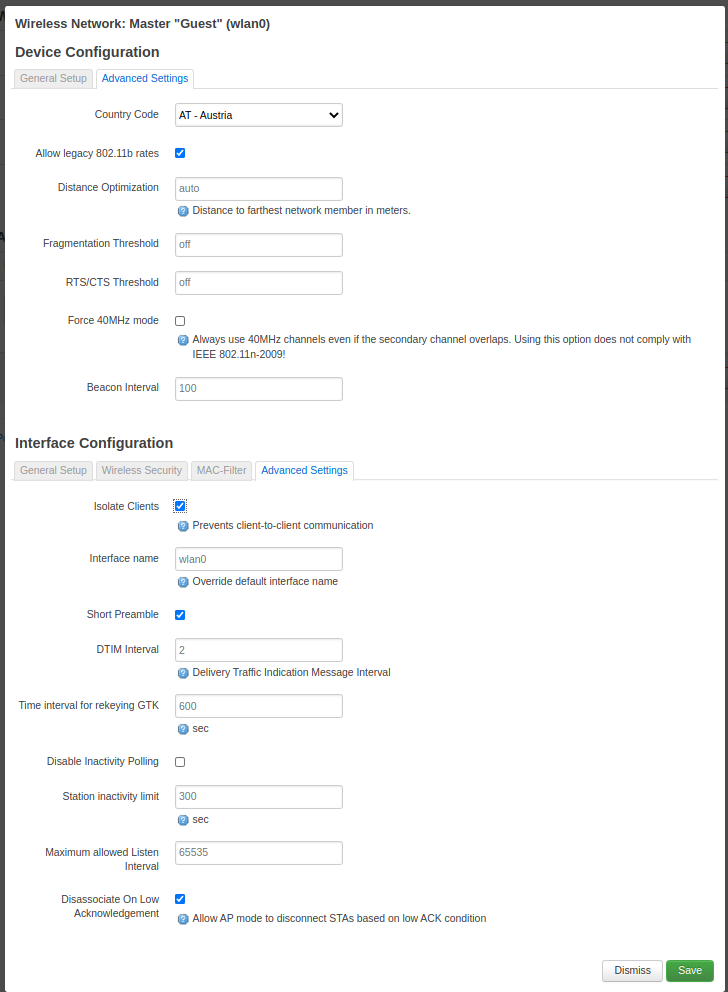
Enable client isolation
Now you should be able to connect to the Guest wifi and get an IP address assigned to your client. Bit it will be pretty boring because there is no internet yet.
Setup the firewall
The last step involves setting up the firewall.
Go to Network > Firewall.
First of all we need to ensure that we have different zones for lan, wan, wifi and guestwifi.
The lan and wan zones are created by default.
We have created the other two zones wifi and guestwifi.
The zone overview should look similar to this.
We can see that the guestwifi zone can be forwarded to the wan zone.
Also make sure that masquerading is enabled for the wan zone (it is per default).
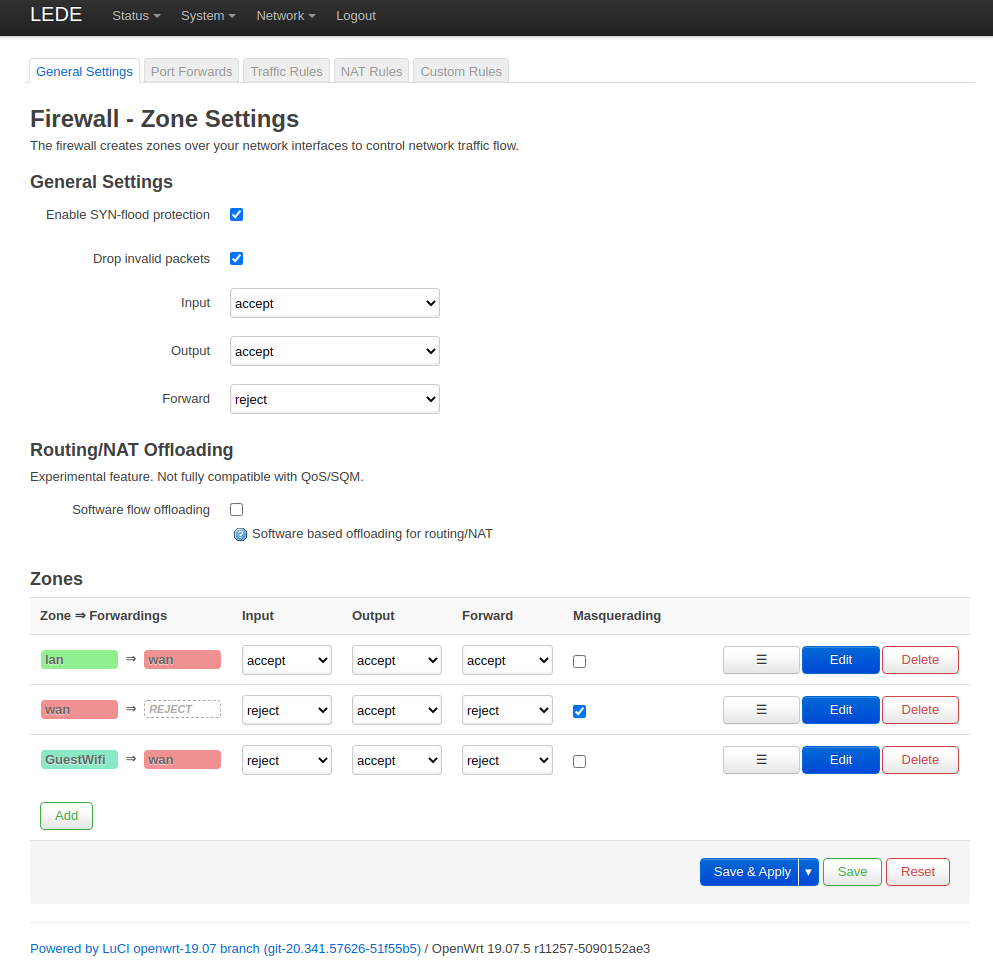
Firewall zones
The details of the guestwifi zone settings are shown below.
Note the default reject settings for the INPUT and OUTPUT chain and that the only allowed zone to forward traffic to is the wan zone.
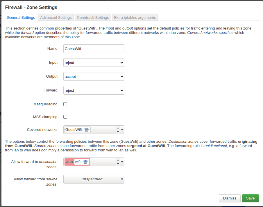
Guestwifi zone details
Now we have to setup three traffic rules in order to enable DHCP and DNS for the guests and to prevent them from accessing the other networks and the router web interface.
Enable DNS
Allow port 53 to be used.
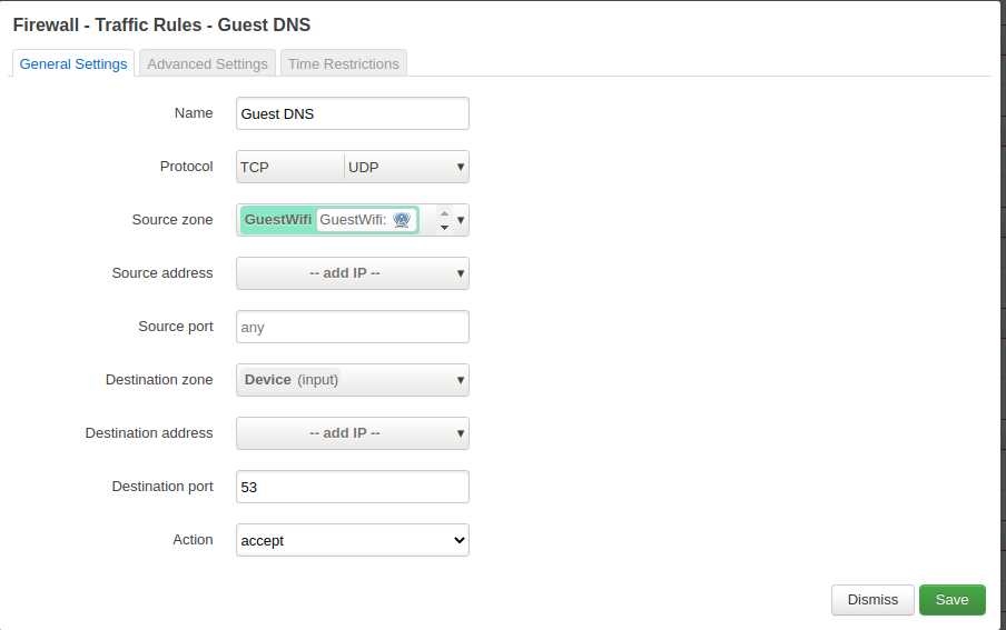
Allow DNS
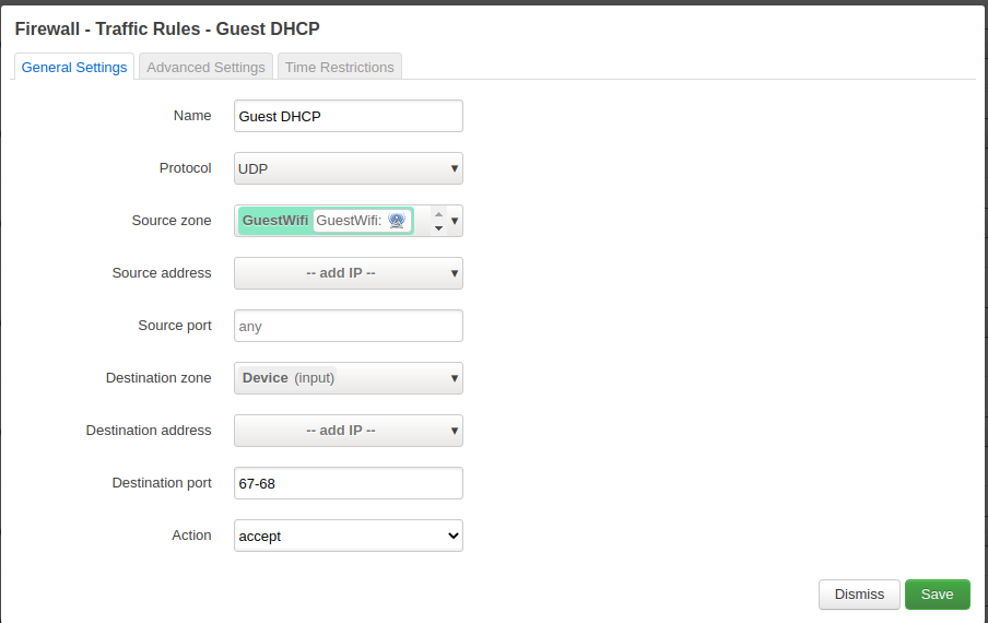
Enable DHCP (ports 67 - 68)
Allow the UDP port range 67 to 68 for DHCP requests.
Guestwifi zone details
Block other networks
In order to separate the guest wifi from our regular wifi and the router, we block the entire subnets.
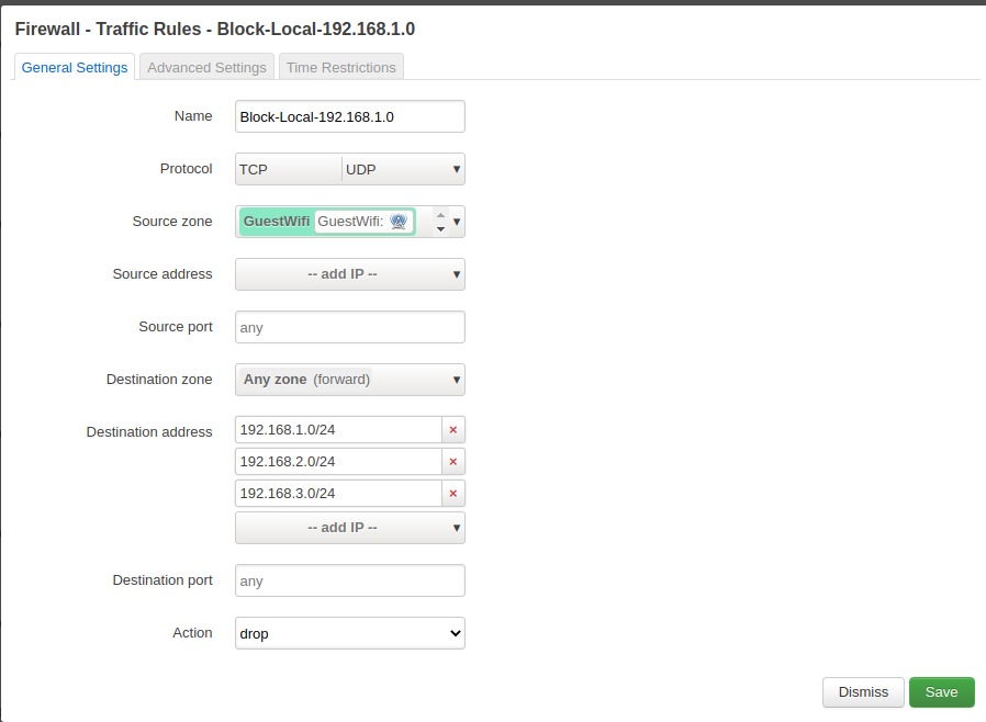
Guestwifi zone details
Conclusion
OpenWrt works very nice once the setup is clear. Some of the naming conventions are a bit confusing, but I guess this is normal given that it is a complex matter. This tutorial shows how to create a guest network on a device which is itself a client in an existing wifi network.